Print-In-Place (Part 4): Lazy Susan with Cylinder Bearings
The Lazy Susan at Last
I initially set out to make a print-in-place Lazy Susan. Cylinders are supposed to print better than spheres, so why not see if I could do something fun with them? It didn’t take long to come up with an idea for how to make a cylinder bearing apparatus (I don’t know what else to call it!).
To turn that into a turnstyle was a little bit trickier. Here is a potential solution. I say potential because I already designed it and it should be off the printer in a couple of hours. But whether it works is a whole other question. Anyhow.
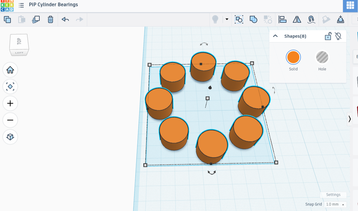
I took a copy of the group of eight cylinders from the apparatus. I broke them apart into eight individual cylinders, a group no longer, though kept them exactly in place.
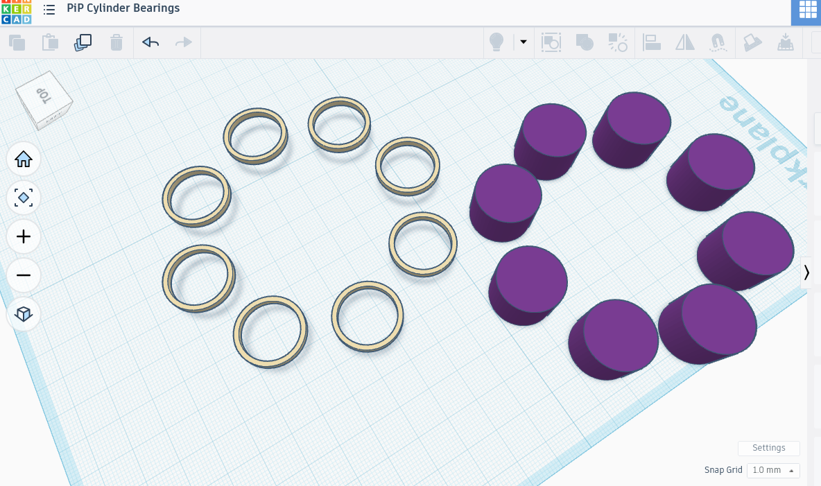
I then turned my attention to the grooves that I planned to run along each cylinder’s center, like a racing stripe. First, a ring for each groove. My first attempt didn’t get very far: I made a perfect ring 20 mm radius, 2 mm high, and 2 mm deep, then tried placing it halfway down one of the cylinders.
I could do that, but it practically blended into the figure. Actually, it did blend into the figure. Not good. Even when parts of a model are perfectly aligned by every method of measurement, the software sometimes has a little freakout when grouping, drawing a hair outside of bounds, or missing a spot. I was going to turn that ring into an eraser to cut out that groove, and could not afford to have it miss even a hair of the outside.
New plan: make the ring a little bit thicker, keeping it’s height. I made the outer cylinder of the ring 20.5 mm radius, using the eraser-shaped inner cylinder’s radius 18 mm. This was a better fit, still pretty snug, but thoroughly covered the outside portion.
It took moving it manually by a quarter of a millimeter in both directions, but I managed to sit that ring exactly on top of a cylinder. I made a quick copy and positioned it the same way, but on an opposite cylinder. Next I grouped the pair, duplicated the copy, and rotated it 45 degrees, rinse and repeat twice, the same way we made the group of cylinders.
I grouped the rings together afterwards, so now I had group of eight cylinders, and a group of eight rings resting on top of them. Once the align tool got those rings exactly halfway down the cylinders, I turned the rings into eraser shapes and grouped the two sets together.
I then put the whole assembly back together.


Last step, the experimental one: I made a 1 mm thin plate with a 55 mm radius, and added it to the rest of the project. I centered it on all three axes; in theory this plate will stay up because the grooves on the cylinders will hold it up.
Anticipating that the design will probably work, I made the final piece: the rotating plate. It’s made of two joined parts: a 53 mm radius cylinder 12 mm high, and mounted by a 2 mm thick 100 mm wide plate. Ideally it will sit on the center plate of the assembly, where the cylinders will allow the fat cylinder to spin. It’s not part of the print-in-place however; it’s something I can add!
I am not sure if there will be enough pressure to hold the plate; I can provide a little bit more by placing the assembly in a snug cylindrical casing, but that’s just in my mind for now, and hopefully won’t be necessary.
Result:
I added too much gap, so the pieces fit rather loosely. This wasn’t terrible, except that it was hard to put pressure on either side of the bearings. I did make an outer shell, as planned for just this possibility, but they were still too loose to be pressed firmly into the plate.
Pressing the balls firmly towards the center with my fingers made the ensemble tight enough that I could test ability of the plate to spin, and it seemed to work rather well.
To make this work properly, without having to resort to fingers instead of good design, I need to shrink the gap between the inner and outer ring, but only by a bit. Unfortunately I’ve already tested quite a bit of filament on this, so any more experiments will have to wait!
If you want to make this for yourself, I think that making the outer ring a fraction smaller is the way to go. It’s what I plan on doing when I decide to come back to this.