Print-In-Place (Part 3): Cylinder Bearings Design and Testing
The Decision
I decided on the cylinder version; it may have been objectively a worse choice, but it looked like fun. I made some notes and sketches, then turned them into a technical drawing, complete with dimensions and views. The basic idea was the same as that of the tutorial, though with a track instead of a torus, and an added cage to keep the cylinders from touching one another. Please ignore the coffee stains; it was the last page in my sketchbook for a reason.

Technical Drawing on a Dilapidated Page
I was working on the cage, a holed disk sandwiched between the top and bottom layers, when I realized that these cylinders were aligned on the wrong axis to be moving any sort of load. Given their position relative to the rims, the only parts of them that were exposed were their tops and bottoms, which would spin in circles. They would probably stop moving at all rather quickly, as they can’t possibly move in the same direction and still spin the plate.
I could do the design without the cover. Normally that would be a disaster, as the cylinders would go flying, but earlier I saw this amazing design for 3D printing ball bearings on How to Make 3D Printed Ball Bearings. I want to modify it, plus make it print in place.
I am sure I can make a coverless version, and it will be cool. It won’t be the Lazy Susan base I had in mind, I’ll do that next, but this one looks too good to pass up. I particularly liked the idea of having ball bearings on the outside, letting the cage double as an outer ring.
Here’s how I see the setup in my head: two concentric rings, each with rectangular slots of negative space all the way ‘round each ring. The cylinders will be between those rings, where the pressure will keep the set in place, though the wheels should be able to spin freely along the rims.
I’m out of sketchbook paper, that was my last sheet! I’m gonna throw something together right onto Tinkercad’s workplane; if it works I’ll formalize it and make it better. Probably on printer paper, ew.
Making the Cylinder Bearing
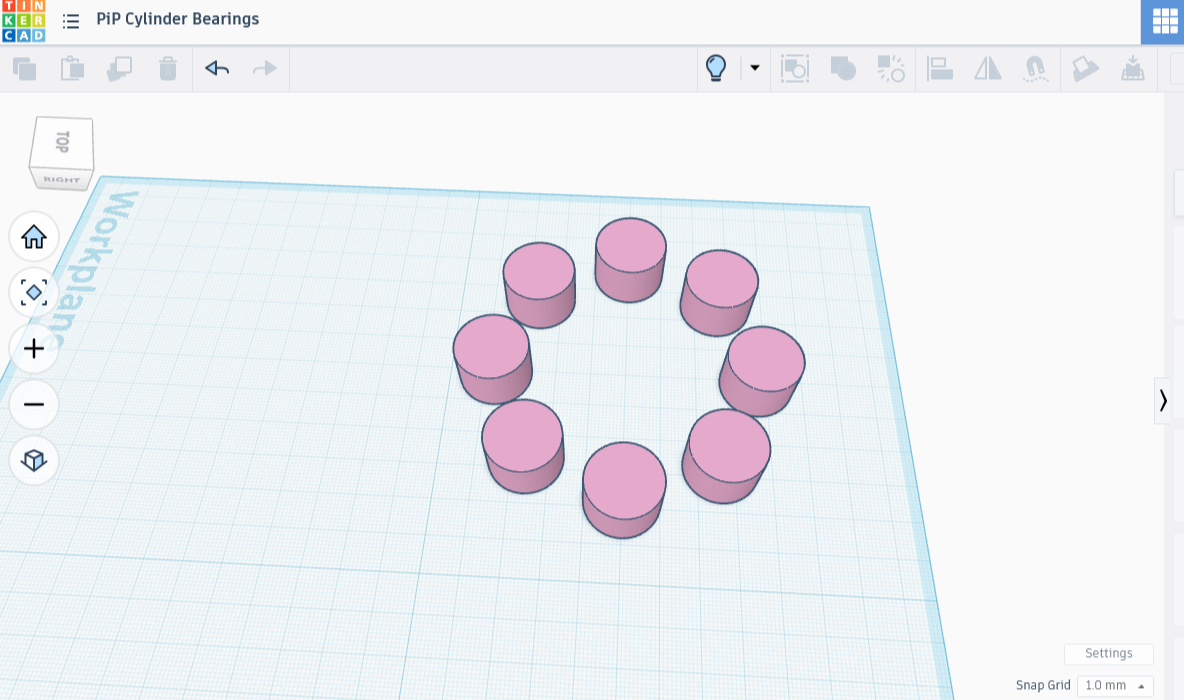
The earlier tutorial started with the track shape to make sure that the ball bearings were appropriately spaced; I’ll take a page from that. I slapped down a 100 mm diameter cylinder, followed by a smaller one that I changed into an eraser. I then combined the two, creating a nice wide ring shape.
Next, I’m going to change the ring into an eraser, except I’m not going to erase anything. Instead, I’m going to use the transparency of this shape to visually align the cylinders inside it, ensuring that they are a good fit. Of course, I need some cylinders first.
I grabbed a cylinder shape, leaving the diameter 20 mm, but lowering the height to 14 mm. I took this moment to lower the see-through ring shape so that it wouldn’t keep me from moving the other pieces. Five mm high should do it without affecting the ability to accurately place the cylinders.
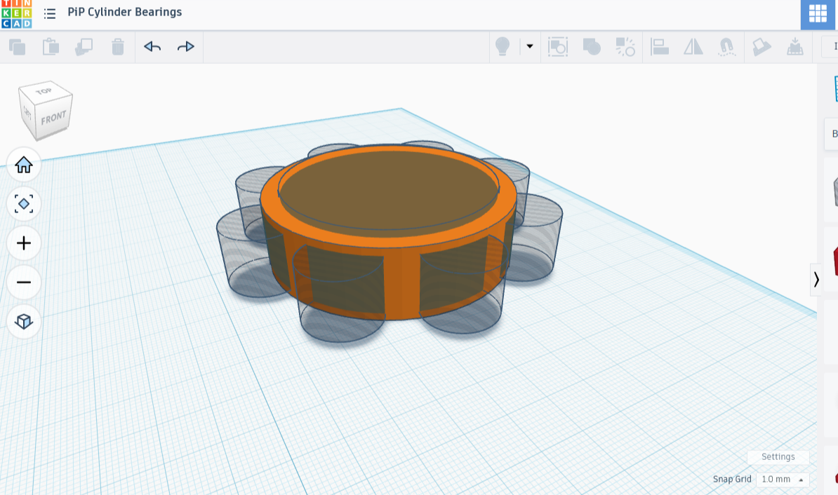
I dropped the cylinder model onto the ring, making sure it stayed inside the ring’s boundaries. I then made a copy of the cylinder, placing it on the opposite side of the ring, centered carefully so that it didn’t touch the ring walls. I grouped the pair of cylinders, ignoring the flat empty disk below. I then duplicated the pair, and before letting go of my selection, I used the rotate tool to move the new pair 45 degrees. I repeated the duplicate/move/place step a couple more times, til I had four pairs (8 cylinders). I then grouped these together, so I had eight total cylinders all together.
I looked at the ensemble from underneath the workplane, and the spacing was clearly good.
I then aligned the whole thing on all three axes, leaving the cylinders floating in the middle of the casing. They were way too short. I decided to bring them up to 16 mm in height, then repeat the centering. Wow, it looked amazing in that casing. Check out that fit! I am feeling rather optimistic.


It’s here that things got a little fast. I actually have my piece printing now and I hope it works. If so, you get specs! Otherwise it’ll be one of my Failure Footnotes ™.
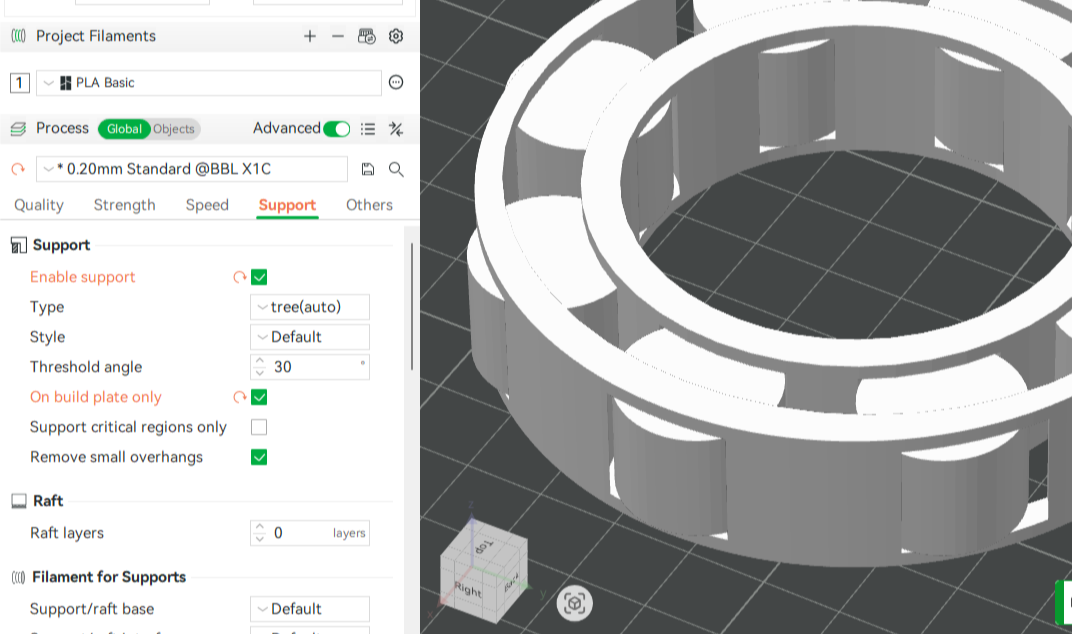
A quick note before printing: On the printer Support tab, I checked ‘Enable support’, opted for tree supports (auto), then checked ‘On build plate only’. No assembly doesn’t necessarily mean no support removal!
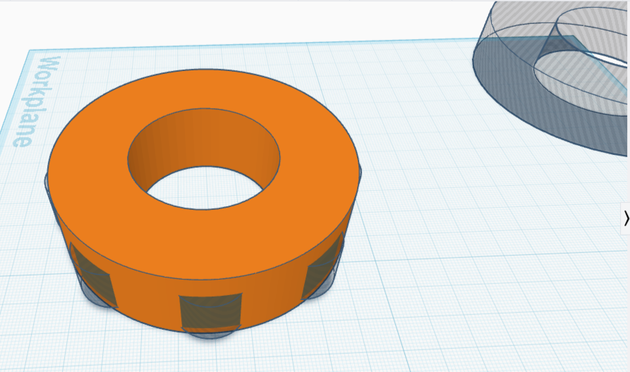
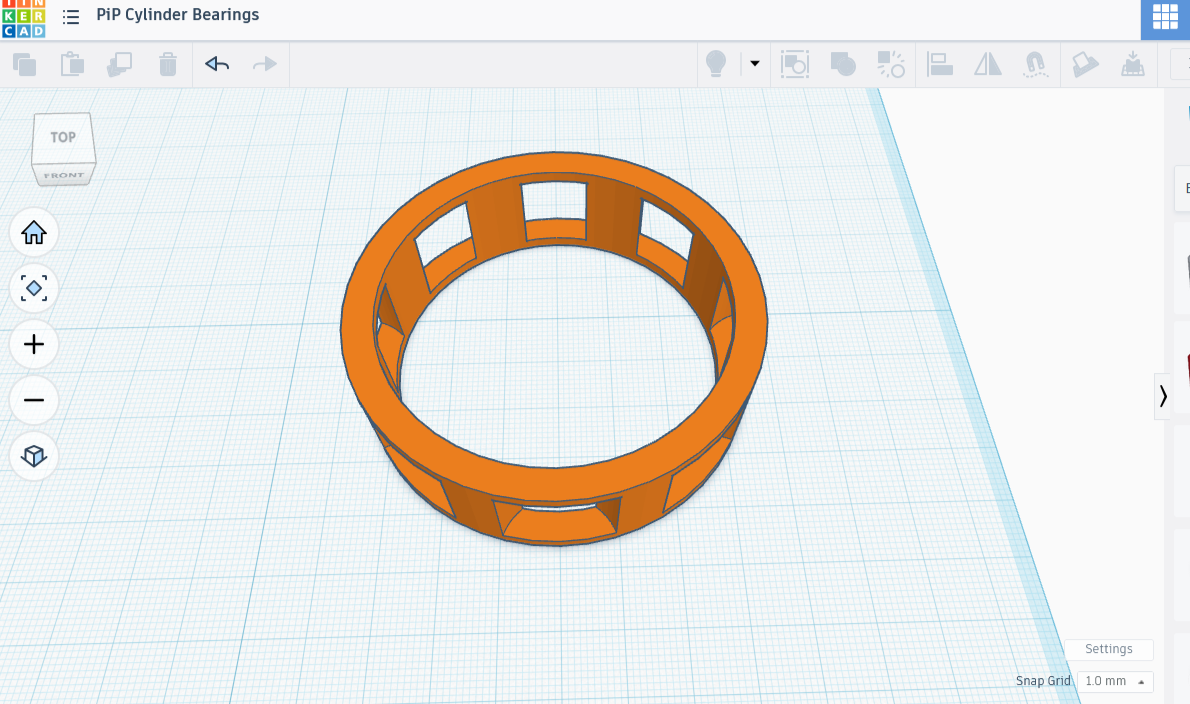
Result of the Rush Job
Well, it was super cool, except for a little user error, which you can see in the image above. I somehow offset two pairs of cylinders; the outer gap on four cylinders is positioned so that it acts as a permanent brake. On the other hand, the four with perfectly placed gaps spin freely on both inner and outer rim.
The cage works exactly the way I thought it would, and there is a little bit of springiness in the cylinders thanks to the tolerance. If I put a round thing of the right size in the center, it can spin. Likewise, if I surround this piece snugly with a cylinder, the outer cylinder will be able to spin around it. Not perfect, but functional. I’ll take it!
I’m going to touch up the design, then share the method and specs. Build-plate only was an excellent choice, as removing supports was easy and mess-free.
On Build Plate Only
Touch-up and Specs
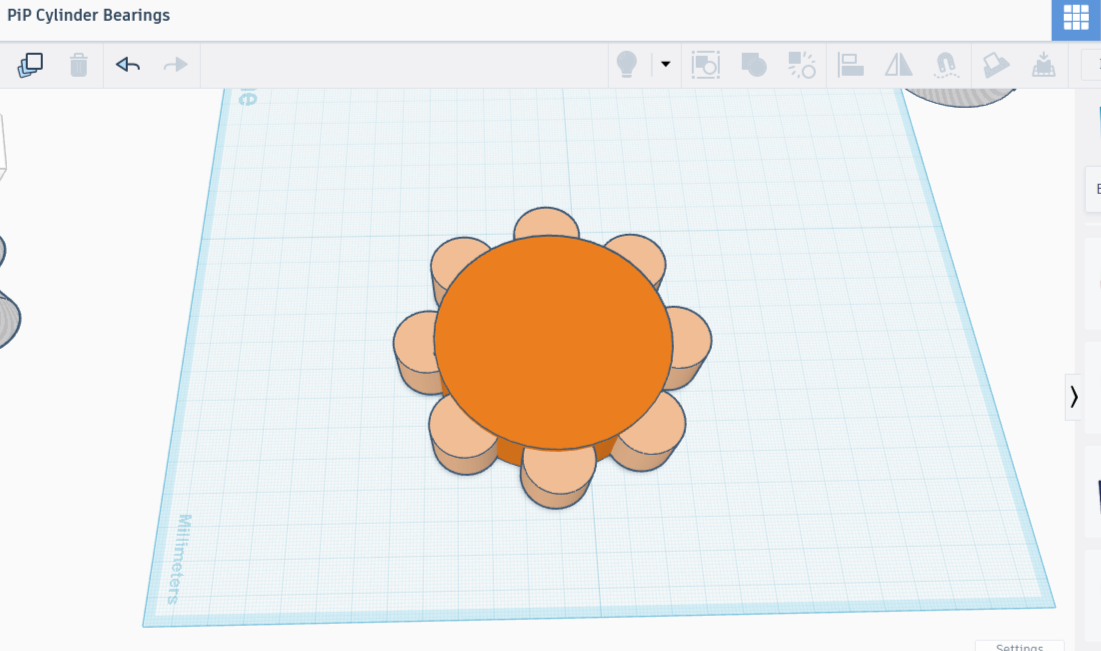
I went back to Tinkercad and opened up the design, where I dissected it. I did that last bit in such a hurry that I had written nothing down. Knowing what the error was (a badly resized cutout shape), I just deleted that grouping and I’ll make another one. We can pick up where we left off. Right now our cylinders should look like they’re in a jello mold, completely surrounded by material you can see through (the 100 mm disk-shaped eraser).
You are going to need the group of eight cylinders again; it’s important that you keep a copy of this on your workplane (click it, then hit CTRL+H if you want to make it temporarily invisible).
After copying the group of eight, I created a large cylinder that engulfed them, changed the cylinder’s height to 25 mm, then began shrinking the radius until about a fifth to a quarter of the outer curves of the group of eight peeped through. It ended up being 90 mm in diameter. I set the original 100 mm disk aside, leaving me with the smaller but taller one and the group of eight. I lowered the height back down to its original height of 20 mm.
The inside of the ring still needs crafted. To make rims 5 mm thick means we need a circle 10 mm diameter smaller than the outside. We’ll add that to the two shapes already out, make sure the lot is properly centered (and sized!), turn the new one into an eraser so as to carve out the middle, and combine the lot. Ta-da! We completed the outer ring.


Now for the inner one.
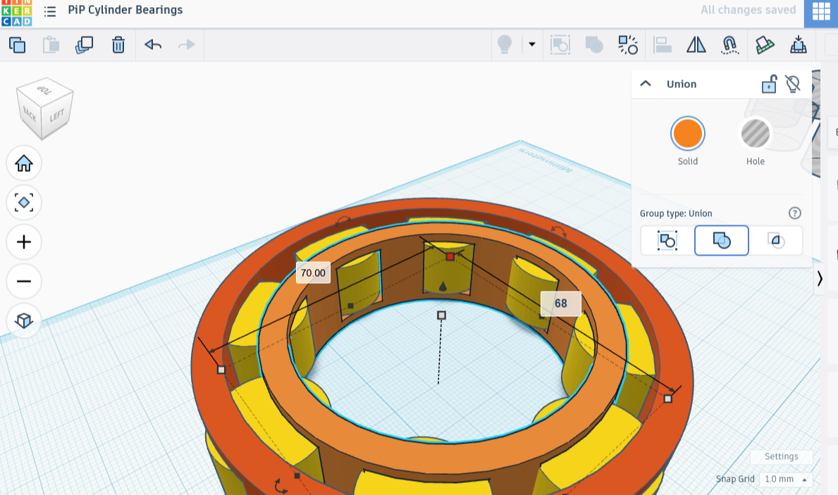
I took the copy of the blob of eight, made and set aside a copy of that, then created yet another cylinder. This one I shrank in diameter until it covered about a fifth of the inside of the eight-pronged figure. It worked out to 70 mm radius, though the prototype was only 65 mm.
To make this inner portion 5 mm thick, the cutaway portion of cylinder would have to be 10 mm radius smaller than the outside, so 60 mm across. I made the appropriate cylinder, centered it, along with the blob and the 70 mm radius one. I then turned this one into an eraser shape, along with the group of eight cylinders. Grouping those two shadow forms with the solid 70 mm ring created a perfect inner band.
I took up the last copy of cylinders and placed it between the two rings. It looked very nice. There was only one (anticipated!) problem: the rings and cylinders had no gap at all, so no spinning would happen. No problem!
I expanded the radius of the outer ring to 95 mm, while shrinking the inner radius to 65 mm. Would that I had written down my tolerances; I was on fire and had no time for such (important) mundane things! I’m going to print this one now. It looks great, no weird gaps.
Print time!
Bibliography
Learn Everything About Design
How to Use Parameters to Design a Print-in-Place Roller Bearing
YouTube
April 10, 2025
blackcat275
r/coolguides, Different Types of Bearings
3 years +
Positive Attitude
How to Make 3D Printed Bearings
Youtube
July 10, 2024