Making Some Ball and Socket Joints in Tinkercad
Have you ever wanted to design ball and socket joints that resemble human fingers? Neither have I, but it’s the next exercise in a book I’m reading. Specifically I’ll be creating 3D-printed movable phalanges, or finger bones, by printing a mostly-rectangular ‘palm’, some socket ‘knuckles’, ball joints on fingers, and some fingertips. The sockets will perform a similar function to ligaments in the human body, allowing the fingers to move. Neat, and also creepy. But neat.
The point of this exercise is to learn the use of the ball and socket joint tool in Tinkercad. The socket looks a lot like the end of a wrench, being shaped like a clamp, but with the inside shaped to hold a sphere instead of being rather squarish.
I can see how it will work. A sphere with a protrusion will go into the sphere-shaped slot. The sphere can rotate in circles, but the walls of the clamp keep it from going too far in any one direction, save for one: the one with the gap. The sphere can spin in that direction because there is room for whatever is sticking out of it to move.
A gap like that could be useful for something if we want it to be able to rotate down. That same gap would have ruined the usefulness of my camera holder, which needs only to rotate, not drop down.
Ball and Socket Design from an earlier Lab
I opened up Tinkercad, started a new project with +create, then renamed the design to Labs III.
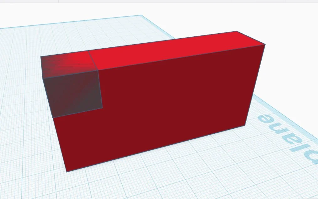
The directions in this book are scant sometimes. It says that the palm is made of two boxes, then gives dimensions of 73mm wide and 16mm. By the picture I’m guessing that those numbers refer to the larger box, and should be 73mm long, 16mm deep, and 35mm high, as the height looks roughly half the length.
For the second smaller box, which will carve out a space for the thumb, one needs to estimate its width. There are five digits of equal size taking up the total space, so the thumb space needs to be 1/5 of 73mm wide, which comes to a little short of 15mm, and 16mm deep, the same depth as the palm, to shadow out a lower spot on the palm for the thumb.
That done, I’m ready to set up some knuckles. The menu to the right of the workplane has tons of shapes and a handy search bar - I used the search function to find the correct sockets. Easy find, hooray! I pulled one onto the workplane, went to copy it four times, and encountered resistance. These shapes can’t be duplicated - they are marked ‘Scaling Locked’.
‘This shape is sized for real components and cannot be scaled’
That’s what it reads on hover. If there’s a way to change the locked setting, it’s not immediately obvious. I manually dragged the other four socket shapes onto the workplane.
I lowered the palm by 35mm, so that the top was flush with the workplane, to make the process of joining multiple pieces to the top easier. After that I slid the pieces into position side by side, aligned them with the aligning tool, then joined the four knuckles to the top of the palm.
I then lifted the palm up just until the thumb socket was positioned correctly, joining that with the larger piece. The next step was raising the whole palm up so that it was sitting on the workplane, knuckles now attached appropriately.
The sockets can’t be scaled but the model can still be re-colored. I went back a couple steps just so I could change the colors because the default was an eyesore. I joined it all up again, and went on to the next step: the fingers!


Four fingers and a thumb, coming right up!
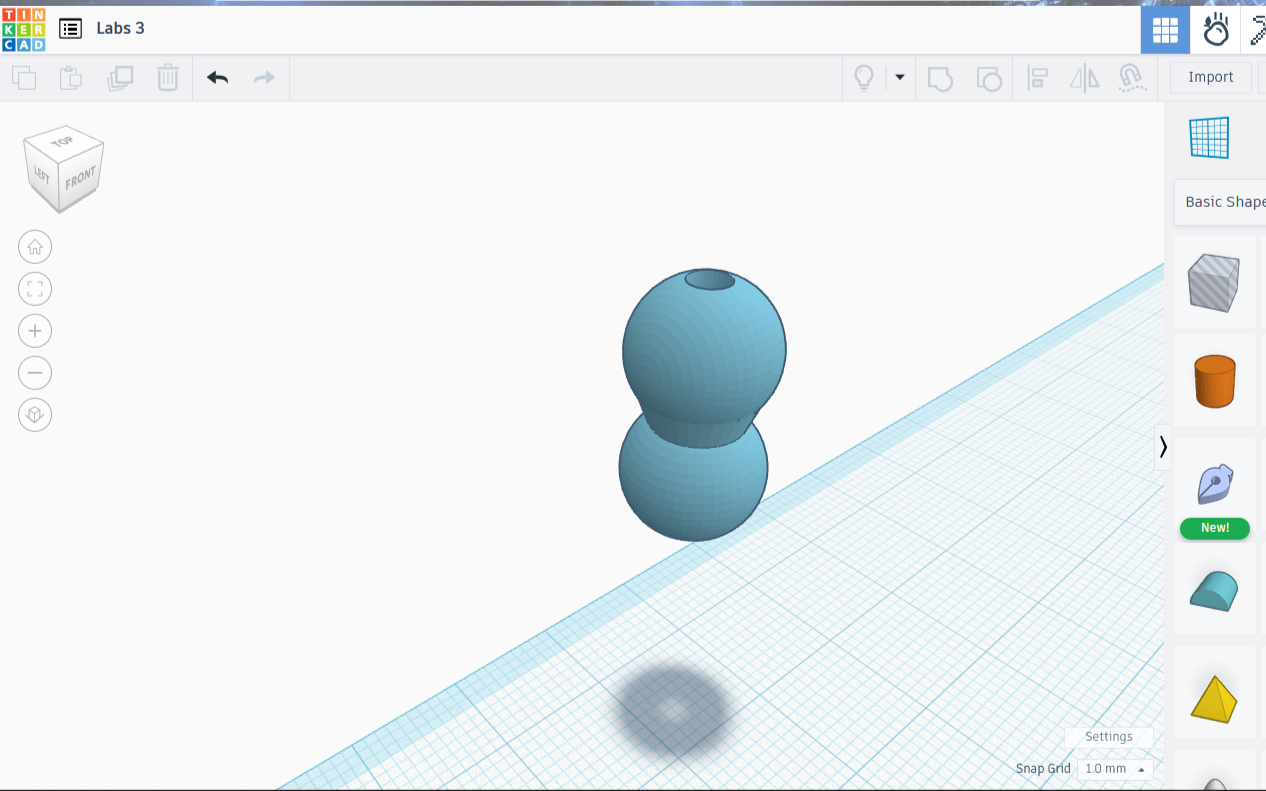
The fingers are made of cylinders attached to the ball portion of the ball and socket. The ball portion is findable by using the search function in the available shapes area. The figure looks like two balls joined side by side, like a solid infinity symbol.
I created a 10mm diameter cylinder, then dropped a double-ball piece ball side down over the center of the cylinder, lowering it until the ball’s equator touched the edge of the cylinder, exactly half the ball.
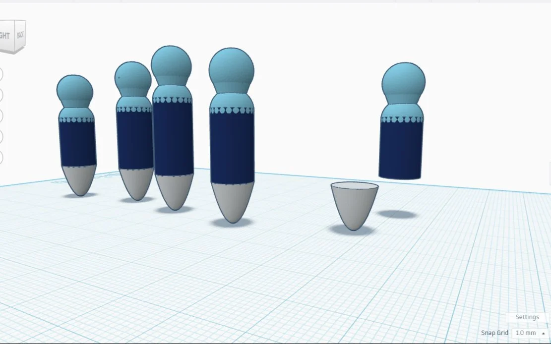
I made four copies of the cylinder, then decided on their needed sizes. The thumb and pinky would remain unaltered. The ring, index, and middle got progressively taller. I then added a copy of the ball joint to each one and combined them.
Finishing the first joint required a set of sockets joined to the finger stubs. It was easy enough to place five sockets under the finger pieces, harder to align them. I ended up looking at them from underneath the plane to ensure they were aligned properly.
I made a copy of each finger stub, intending to use the copies for the next and last set of knuckles. I then set the copies aside and focused on finishing this set. With all the pieces aligned it was easy enough - I simply combined each pillar separately.
The last step involves adding fingertips to the last set of knuckles. I used the paraboloid tool, resizing the odd shape so that all dimensions read 10, copied it four times, and placed a ‘fingertip’ on the end of the newest set of knuckles, so completing the project.


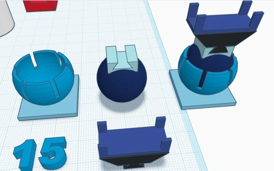
The pieces are meant to be printed separately, then put together. I put them together in Tinkercad in order to show what it could look like if finished, although for purposes of this project I am already done.

A Hand, with Movable Fingers