How to Create a Technical Drawing for 3D Printing Projects
I wanted to learn standards for creating technical drawings. The very first hit was a Youtube video by Jason Erdreich, also author of Taking Tinkercad to the Next level, a book that I just started. What a wild coincidence, so cool! I like the author’s presentation style, which carries over to the video.
I took notes, and I’ll share some highlights, but I recommend watching the video yourself for the full experience. It’s quite informative.
According to my notes on the video, a basic technical drawing has four sections, each for a different view of the model. Three of the panels show what the model looks like from the top, front, and right side. These views are orthographic, or 2D drawings of 3D things.
The fourth section is an isometric drawing, showing the model from a 30 degree persective, and is the reason for that oddly shaped graph paper that I’ve seen before in office supply stores.
I also learned that you shouldn’t write any measurements on the isometric view, and that the model front is the side one interacts with or the side with the most information.
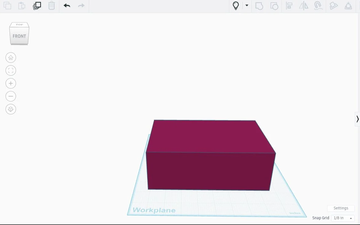
For my first technical drawing, I am using an espresso cup. It still has espresso in it, so the dimensions will have to be added later.
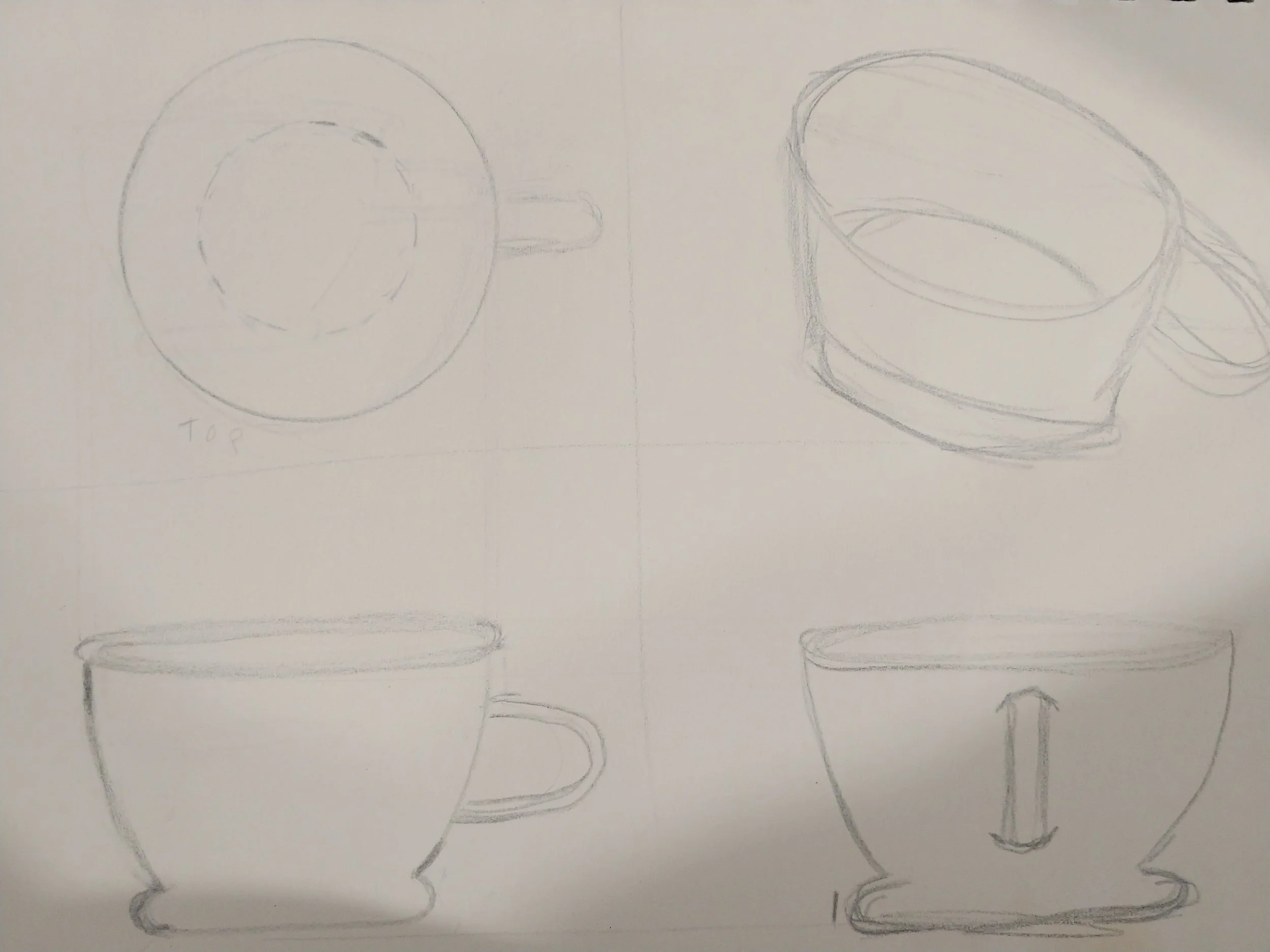
Technical Drawing #1: An Espresso Cup, sans Dimensions
I then found another resource: a website called Worthy Hardware. Let me say, their page on technical drawing blew me away. I am not a customer, but if I were, I would feel assured by the competence and quality on display, as well as the ability to communicate effectively about how to make drawings that communicate effectively.
One interesting feature that’s covered on that page, and that I often see on technical drawings of ordered parts, is that of a title block, though I didn’t know it had a name until now. I thought I’d look into this a bit more.
A quick look online shows that title blocks vary widely, though fulfill the same general purpose, which is to “record all important information necessary for the working drawings. They contain general as well as specific information,” according to McGill University’s article on Engineering Design.
Using what I’ve Learned: Project Toolbox Redux
I made a toolbox recently, and it was a disaster. I feel like a more detailed plan might have averted the problems. I decided to start again, but with a proper technical drawing first. I’ll be honest, I’m a bit intimidated here. I already drew box plans once, but those were rough sketches, with numbers. This time I’m going to make an official Technical Drawing, with a rudimentary Title Block, for each part of the project.
What I know about this box:
it should have two drawers, one on top of the other, and the whole thing topped by a bin with a cover. three drawers of equal size.
the box must be wider than it is long (deep)
drawers and bin are separate but stackable pieces, all the same length, depth, and height
the edges need curvature, partly to avoid potential scrapes and cuts, but also because curves are easier for printers to handle than sharp turns.
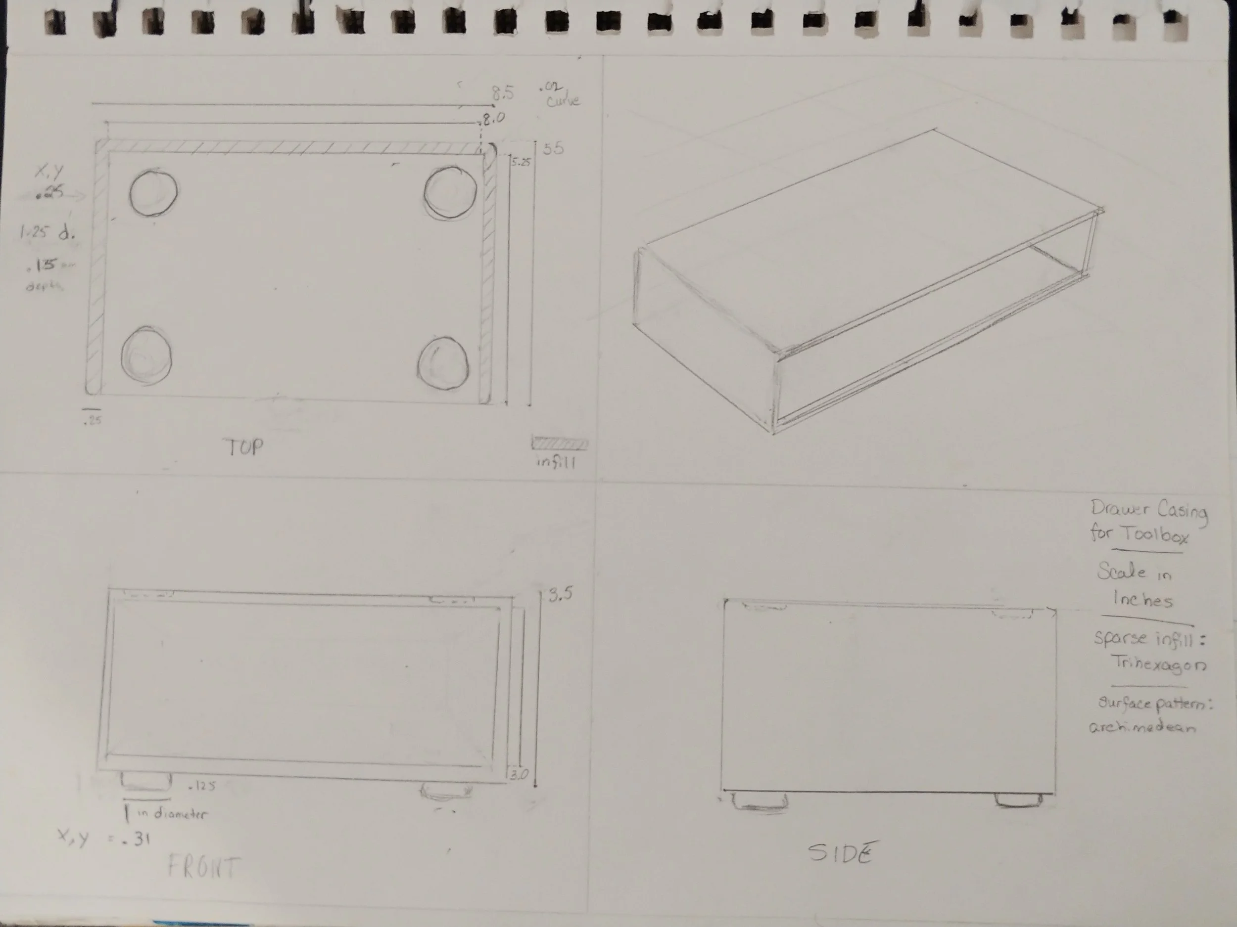
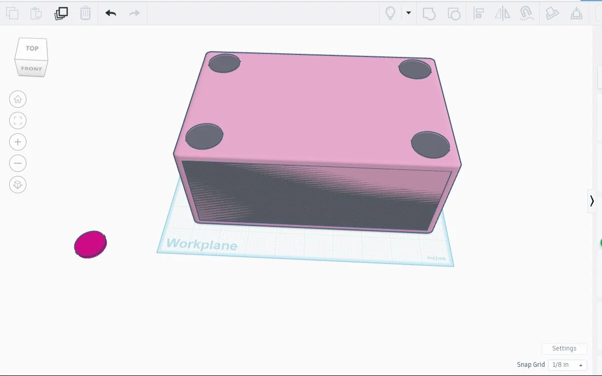
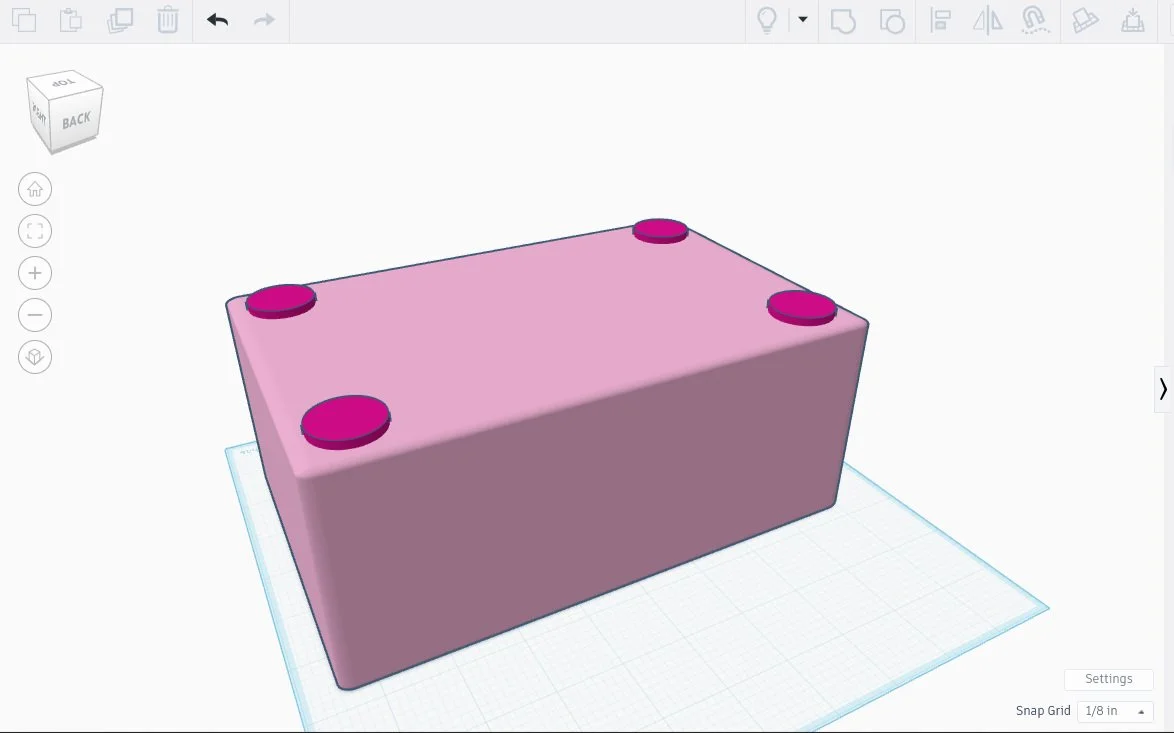
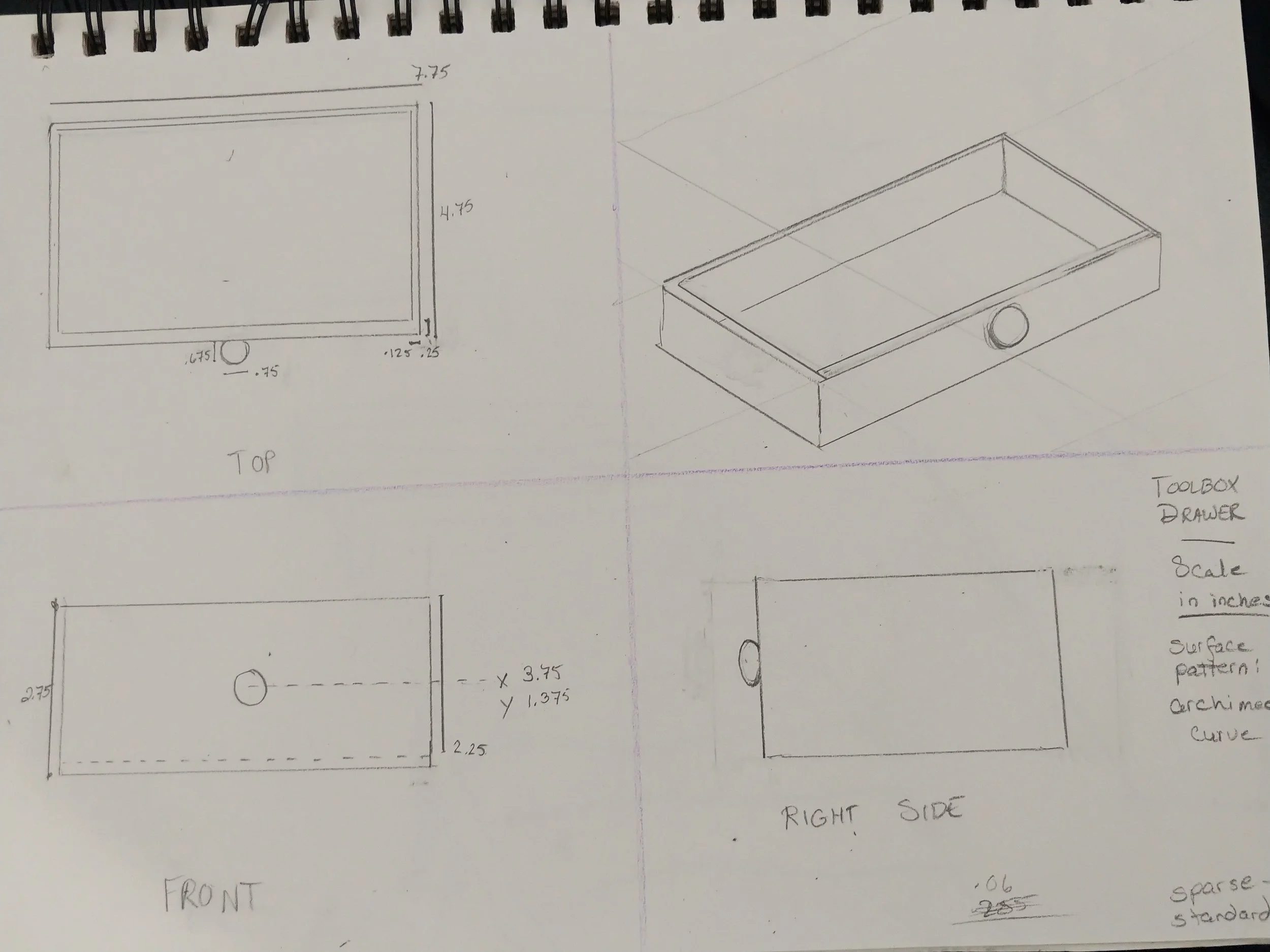
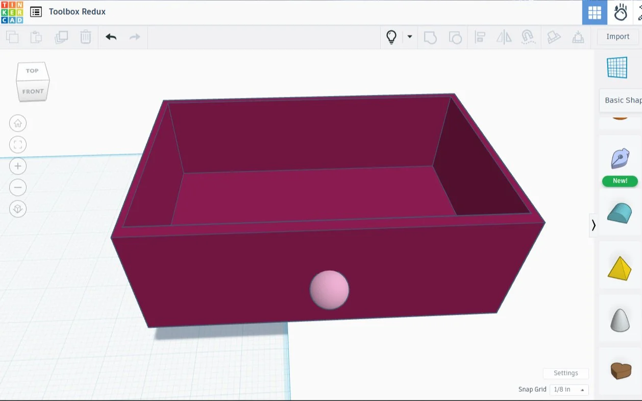
Toolbox Drawer Case
Second Technical Drawing!
Preparation
I got out my sketchbook, a pencil with an eraser, a fine pencil, and a ruler.
First, I quartered the page. The upper left portion will have a drawing of the case as seen from the top down, the lower left will display the front, and the lower right will show a side view.
On the upper right I used my ruler to draw a faint series of 30 degree lines for use in an isometric drawing.
I then spent some time drawing up the dimensions:
Dimensions in inches (drawer case segment):
OUTER PORTION - 8.5 inches wide, 5.5 inches long, 3.5 inches tall (solid, with curve of .01?)
thickness of wall - .25
leaves empty space inside, 3 inches from top to bottom, 5 inches deep, and 8 inches wide - NEGATIVE SPACE FOR DRAWER
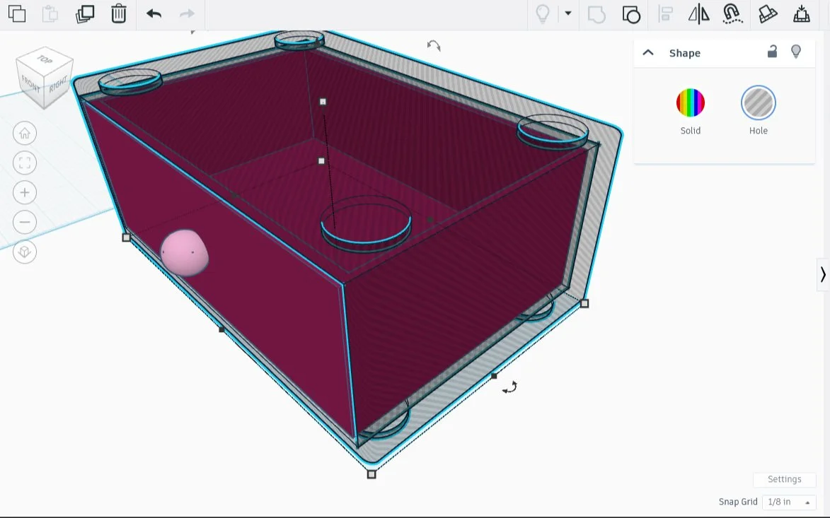
Foot sockets (drawer case segment):
ON TOP - circle 1.25 inches diameter, .15 inches deep
.25 inches space between circle at widest point, and wall.
radius of circle (.625) + .25 = .875, distance centerpoint of circle needs to be from the edge on all four corners
Feet (drawer case segment):
ON BOTTOM - circle 1 inch diameter, .125 inches deep
.31 inches space between circle at widest point and wall
radius of circle (.5) plus .31 = .81, distance between centerpoint of circle and both corner walls, applicable to all four corners
With that done, I was finally ready for the drawing part of the technical drawing.
The Top
In the upper left portion of the paper, I sketched out the case would look like from the top, with no shading and a single perspective. Along the image I drew lines that were equal in size to the length and depth on the image, then tagged them with the appropriate dimensions, making note of the infill by giving it a diagonal pattern on the drawing.
I made a note on the diameter of one of the feet, as well as it’s height, then noted how far the center of the circle was from the edge of the case.
Lastly, I wrote ‘.02 curve’ near the corner because anyone using Tinkercad can feed a number into a rectangle shape to round the corners, and .02 gives the needed amount of roundness.
The Front
What would this box look like from the front? It would be a box with a slot in it, and the round feet on the bottom would probably be indistinguishable from rectangular ones.
In the lower left section of my page, I drew the box, with a box inside it to represent the empty space. I then tagged the height dimensions, something I hadn’t yet marked on the drawing. I did take the time to line this drawing up with the one below it, making sure they matched size on the dimension they shared.
The Right Side
In the lower right corner of the page, I drew the view from the right, positioning it so that the side and front views aligned at the height level. All the dimensions were covered in the first two boxes, and repeating them is unnecessary, so that view was done rather quickly.
An Isometric View
The isometric view belongs in the upper right corner. This view is a 3D representation on the model, done in two dimensions. There is no vanishing point, nothing shrinks, but it is a good opportunity to add a little shading etc.
I drew the drawer case using my near-invisible lines from earlier, adding faint dashed circles where the feet would be, and shading in the holes on the top, so it was more apparent that they were in fact holes.
Title Block
I feel like I should have one - kind of like commenting code, it’s useful because I am certain to forget things, like what this is for, who this is for, what the scale is, and what infill patterns are optimal.
The information in them varies by company, and seemingly no two are alike. Mine won’t need much, I think. I took some notes and put them in the bottom right, near the SIDE view. It’s likely the most informal title block anyone has ever seen, but it’s there!
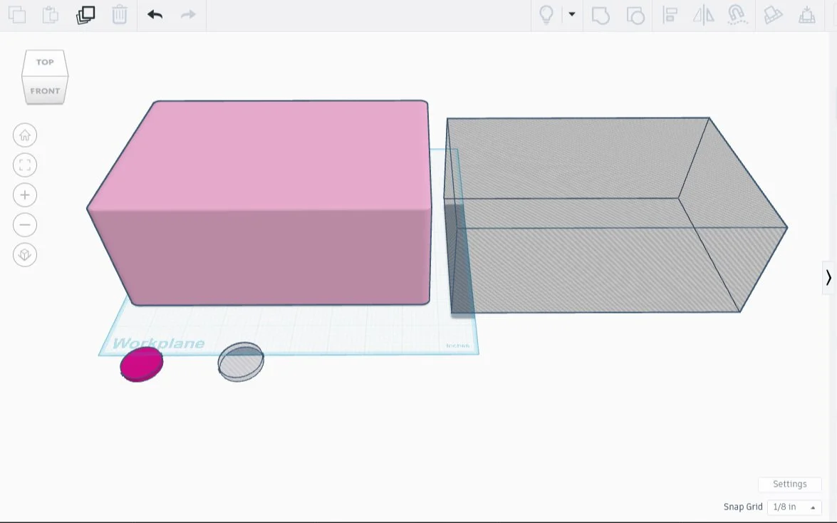
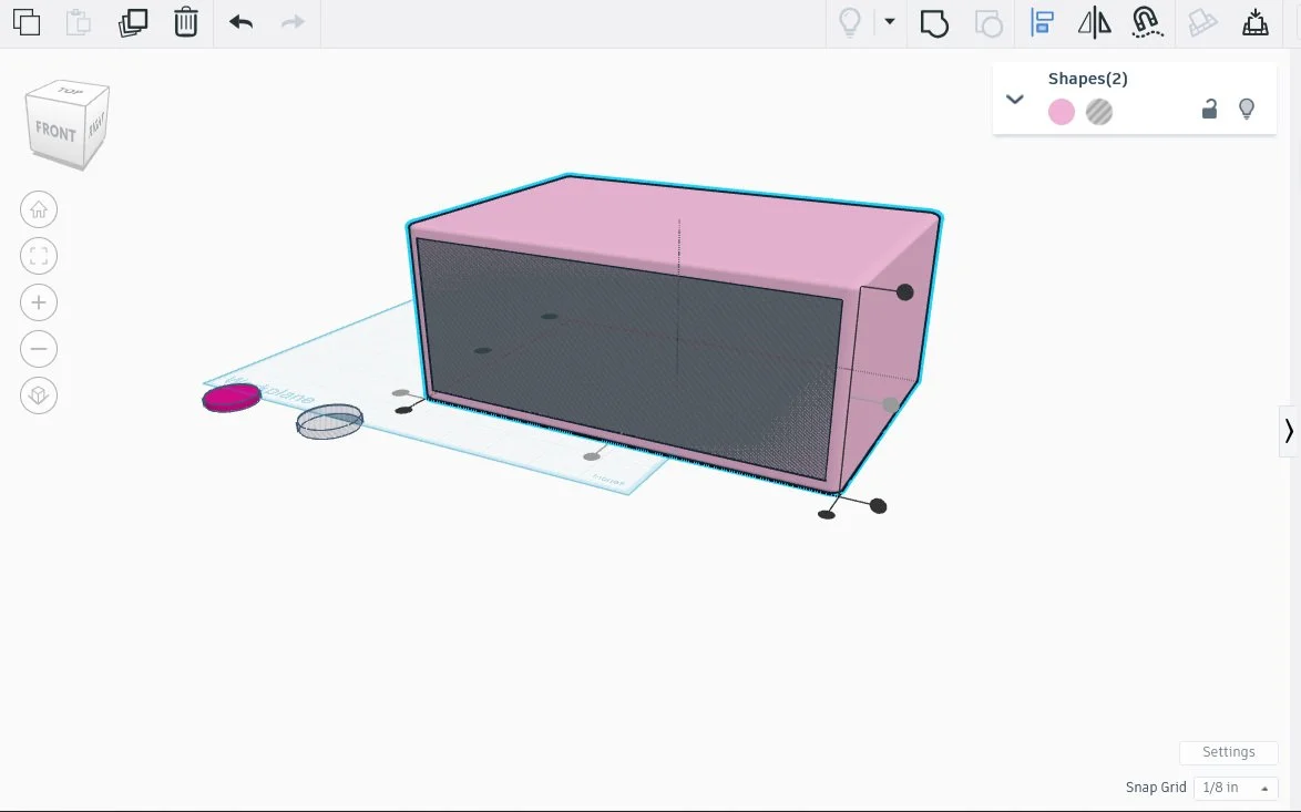
I then went to Tinkercad, and there turned my drawing into a Real Printable Object, using the dimensions I had worked out earlier.
I made a thin slice of both top and bottom, so as to test the feet before printing.
The work so far is cluttering my workspace, which gives me the opportunity to use a nifty new trick I learned: CTRL-H. It hides away whatever I highlight, and the parts stay hidden until I click the light bulb icon and reveal everything. One click and a shortcut later, and my workspace is clear again.
I’m going to start work on the drawer itself while the test feet print. When it’s done, I will reveal the drawer recess, then test out the fit in Tinkercad before I even think about slicing a bit off for testing the space. If that sounds like a lot of testing, well, it’s better to test a small section first than to waste oodles of print material and time, something I wish I had done on this project in the first place.
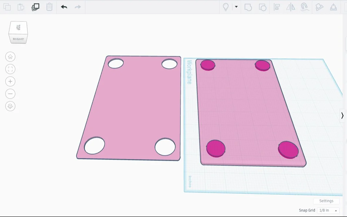
Toolbox Drawer
3rd Technical Drawing
The drawer that fits in that space will need wiggle room (tolerance), .125 inches per dimension, so a 2.75 x 4.75 x 7.75 rectangle is the perfect size for the DRAWER
the walls of the drawer will be .125 thick on the left, right, and back panel, and .25 on the front and the bottom.
TEST FIRST, with a slice of the drawer inside a slice of the slot. Does it fit?
Final dimension of width inside the drawer (negative space): 7.25 x 2.5 x 4.375 width 7.75 - 2(.125) or 7.75 - .5 = 7.25, Height inside drawer: 2.75 - bottom (.25) = 2.50, Length (depth) of drawer: 4.75 5.125 - (front + back) = 5.125 - (.375) = 4.75
Knob (handle) - .75 inch diameter sphere, with .125 inches in the wall
Socket set-up so that the drawers slide - Unnecessary, never mind
To see the fit, I made the case invisible using the hole option, then slid the drawer into place. Seeing the drawer through it’s case made me realize it was far too short. I added another .375 inches to the depth, tried again, and it looks great. A snug fit, with perhaps a bit of wiggle room.
Now to change the case back, and save my work. The printer is still occupied.
I’ll know when the print is done whether or not it was successful. Regardless, I’ll post the outcome!
I did end up deviating from the blueprint during production. I changed the amount of depth the drawer had, as well as the amount of space the feet were from the edges.
Having technical drawings made the work SO much easier, goodness. It took far more time initially, but I was able to anticipate most potential problems before they saw the light of day. I realize mine are baby steps, but I feel really good about this. Creating a technical drawing for each of the 3D printed parts helped me avoid some of the earlier problems.
The FOLLOW-UP
The feet fit into the slots, but they would slide around a bit, meaning there was more wiggle room than I wanted. I scaled the foot size up by a hair, test-printed that, and it fit beautifully: the feet snap into place now. Also - testing cost, around a dollar. The empty case, closer to twelve dollars. Testing is good.
All kinks worked out, I started printing, but my printer jammed a couple hours in, grr. This particular filament was extremely cheap, but it tends to jam in the machine. After an unjam and a filament switch, printing resumed.
Meanwhile, I made technical drawings for a complete box with it’s component parts, then designed them in Tinkercad.
I printed the rest of the pieces, then snapped feet into sockets where appropriate, creating a mini tower for my tools. It looked so nice that I drafted, designed, then printed another one.
The second tower was similar in style, but due to a change I made in the center portion of the box, it required some minor adaptations if I wanted the towers to have the same height, which I did. Having a draft of the final product, all drawers included, made making those changes sooooo easy. It made everything easier every step of the way.
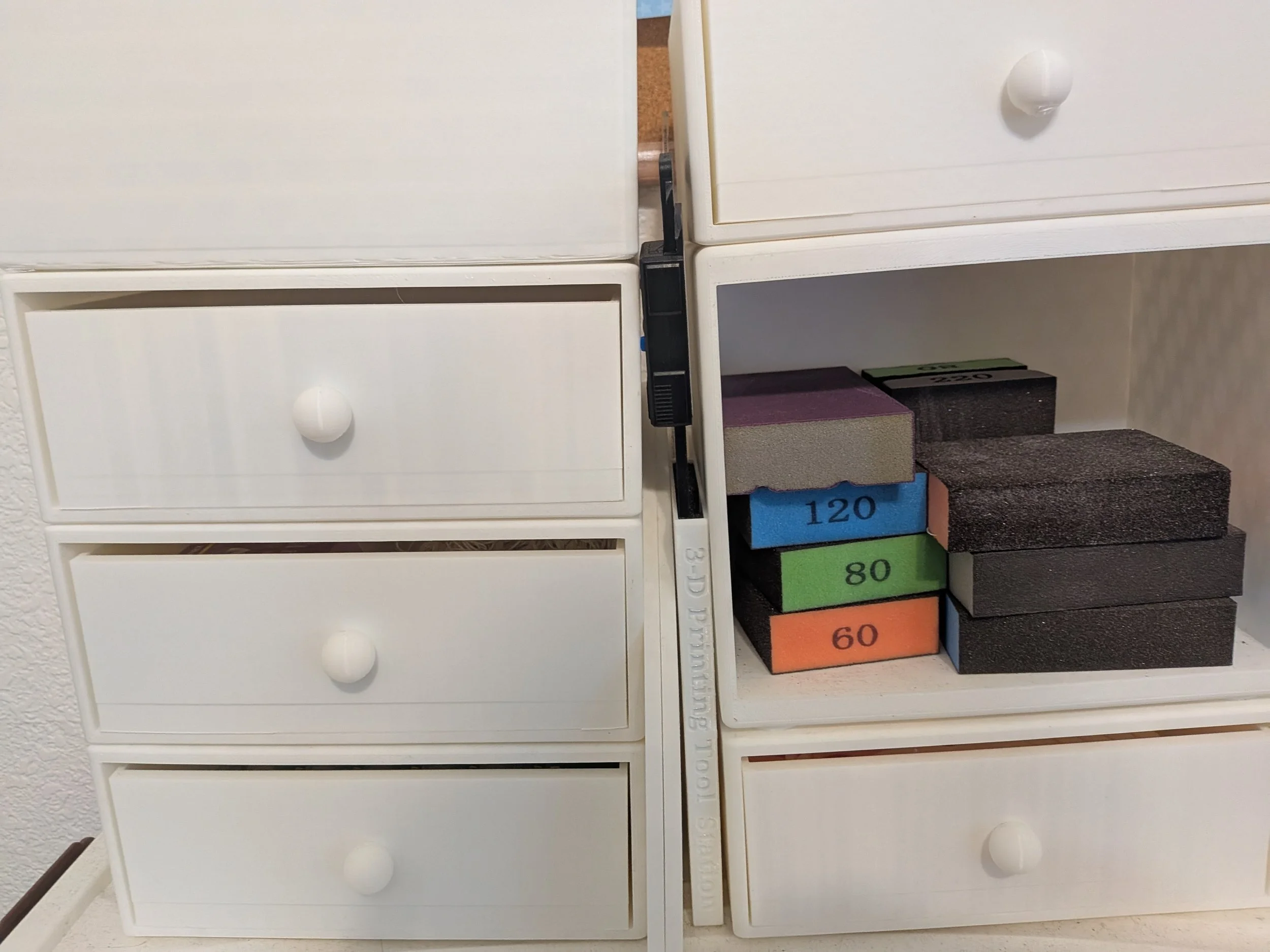
Tower Toolboxes & Accessory Storage - My 3-D Printed 3-D Print Workstation!
Bibliography
Erdreich, Jason
Learn the Basics of Technical Drawing
Youtube
28 Feb 2023
Worthy Hardware
What are Technical Drawings? Everything you Need to Know
Worthy Hardware
19 Oct 2023